
How to Choose the Right Floating Ball Valve?

Time:2026-10-16 Author:Aria
0%

Choosing the right Floating Ball Valve is not simply a matter of matching pipe size. The decision affects safety, flow control, maintenance time, and long-term operating costs. A valve that looks suitable on paper may fail under real process conditions. A neat specification sheet can still mislead.

This guide explains the practical factors engineers and maintenance teams should examine before purchasing. These include pressure rating, temperature range, media compatibility, seat material, body construction, connection type, and operating frequency. For example, a valve handling clean water may use different materials from one exposed to corrosive chemicals or abrasive slurries. Small details matter. Seat damage often begins with the wrong material choice or excessive pressure.

Reliable selection also requires attention to industry standards, manufacturer documentation, inspection records, and installation quality. Experienced professionals usually compare torque requirements, leakage ratings, fire-safe options, and replacement-part availability. They also consider whether the valve can be inspected without disrupting the entire system. That practical question is often overlooked.

No selection is perfect. Operating conditions can change, and published data may not reflect every site-specific risk. For this reason, specifications should be checked against process data and verified with qualified suppliers or engineers. The goal is not to choose the most expensive valve. It is to choose a dependable Floating Ball Valve that performs consistently, supports safe maintenance, and fits the actual demands of the pipeline.
How to Choose the Right Floating Ball Valve?

Understanding Floating Ball Valve Design and Operating Principles

How to Choose the Right Floating Ball Valve?

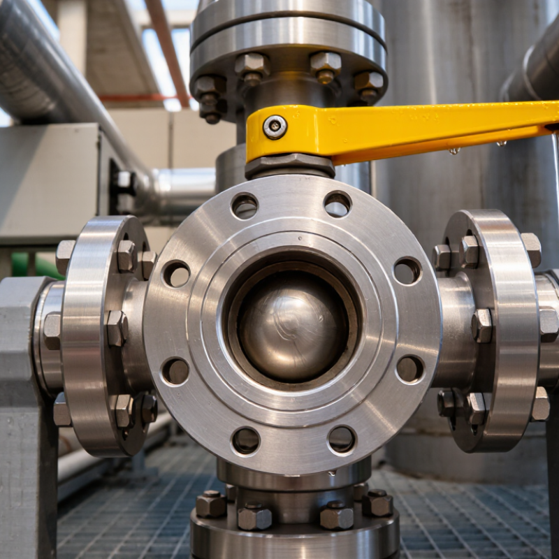
A floating ball valve has a ball that is not fixed to a lower stem support. Line pressure pushes the ball toward the downstream seat. That movement creates the primary seal. The stem only rotates the ball, so operating torque often remains lower than in supported-ball designs. That matters.

In field inspections, I check the seat condition before trusting the valve’s pressure rating. A scratched seat may leak even when the body looks perfect. The valve should match the fluid, temperature, pressure, and required flow rate. Full-bore designs reduce turbulence and pressure loss. Reduced-bore designs can lower cost and weight. Choose carefully. Torque can increase when cold fluids stiffen the seats or when solid particles enter the cavity.

The 2024 Grand View Research Industrial Valves Market report valued the global market above US$75 billion in 2023, reflecting strong demand for dependable flow control. Market growth does not make every valve suitable. API 6D supports pipeline valve design requirements, while API 598 addresses pressure testing practices. These references help verify construction and leakage performance. For automated service, compare actual breakaway torque with actuator output, not only the nominal valve size. My first selection was too conservative on pressure, yet it ignored temperature cycling. That was a useful mistake. A reliable choice also considers fire-safe construction, anti-static features, end connections, maintenance access, and the possibility of cavity pressure.

How to Choose the Right Floating Ball Valve?

Understanding floating ball valve design and operating principles starts with selecting a suitable bore size. The chart compares the theoretical flow area of representative full-bore openings, calculated from A = πD²/4. A larger flow area can reduce velocity and pressure loss, while the final selection should also consider pressure rating, temperature, media compatibility, sealing material, and operating torque.

Values are geometric reference calculations based on representative circular bore diameters; actual valve flow capacity depends on the complete valve design and flow coefficient.

Defining Pressure, Temperature, and Media Requirements

Choosing a floating ball valve begins with actual service conditions, not pipe size alone. Pressure deserves careful definition. Record normal, maximum operating, and possible surge pressure. A pump start can create a sharp spike. Small details matter. Select a valve whose pressure rating covers the highest credible condition at operating temperature. Ratings may decrease as temperature rises, especially with softer seat materials. Never treat a catalog rating as constant.

Temperature data should include startup, shutdown, cleaning, and upset conditions. A process at 120°C may briefly reach higher temperatures during steam cleaning. Check whether the body, ball, stem seals, and seats tolerate that range together. Media descriptions must be specific. “Water” could mean treated water, brine, or slurry. Note concentration, viscosity, solids, acidity, and gas content. Abrasive particles can damage seats and increase leakage. Reactive fluids may require different body and sealing materials. Compatibility charts help, but the process engineer should verify them against current safety data.

During commissioning, confirm that the valve operates at the real differential pressure. A valve that feels smooth on a bench may become difficult under load. Consider whether the floating design suits the pressure and size, since higher pressures can increase seat load and operating torque. Actuator sizing should include breakaway torque, not only running torque. I would question unclear data instead of filling gaps with assumptions. That habit prevents expensive surprises. Still, field conditions change. Review the selection after temperature cycles, media changes, or repeated shutdowns, and document every assumption.

Selecting the Right Valve Materials and Sealing Options

Choosing a floating ball valve starts with the process media, not the pipe size. A valve for clean water may use a stainless-steel body and PTFE seats. Chemical service demands a deeper compatibility review. Corrosive fluids can attack ordinary metals from the inside, even when the exterior looks perfect. Check temperature, pressure, concentration, and flow frequency before selecting materials. Small details matter.

Seal selection often controls service life. PTFE handles many chemicals and offers low friction, but it can deform under high heat or load. Reinforced PTFE may reduce wear. PEEK seats can suit demanding temperatures, though they usually cost more. Elastomer seals, such as EPDM or FKM, require careful media matching. Never choose by temperature range alone. A seal may survive heat but fail after contact with one cleaning chemical. That mistake is easy to make.

In practical inspections, I look for a material certificate, pressure rating, and documented seat test. The valve should open smoothly without excessive force or leakage around the stem. I once saw a correctly sized valve fail early because the seal material was selected from an outdated fluid chart. The specification looked professional. It was not complete. Ask for current compatibility data and consider real operating cycles, not only design conditions. A short review with the process engineer can prevent an expensive replacement.

Matching Valve Size, Port Design, and Connection Type

How to Choose the Right Floating Ball Valve?

Valve size should follow the pipe and the actual flow demand, not simply the existing flange size. A valve that is too small can create excessive velocity, noise, and pressure loss. An oversized valve may operate near its seat, where control becomes unstable.

The U.S. Department of Energy reports that compressed-air systems can lose 20–30% of output through leaks and poor maintenance. A wrongly sized valve can add another avoidable loss. Check flow rate, pressure, temperature, fluid viscosity, and shutoff requirements. Measure twice.

Port design matters. A full-port ball valve keeps the bore close to the pipeline diameter, reducing turbulence and helping pigs or cleaning tools pass through. A reduced-port design is often lighter and less expensive, but its smaller opening increases local velocity.

In water service, I would compare pressure-drop data at the real operating flow, not at the valve’s maximum rating. That distinction is often missed.

Connection type must suit installation and maintenance conditions. Flanged ends support repeated servicing and are practical for larger lines. Threaded ends fit compact, low-pressure systems, but sealant control and alignment require care. Welded connections offer a permanent joint, although future replacement becomes difficult.

API 598 testing and ASME B16.34 design requirements provide useful verification points. Still, paperwork cannot replace checking gasket position, bolt loading, and available removal space. Field conditions are rarely perfect.

Evaluating Actuation, Standards, Maintenance, and Total Cost

How to Choose the Right Floating Ball Valve?

Choosing a floating ball valve starts with the actuator, not the catalog price. Electric, pneumatic, or manual operation must match cycle frequency, torque, power access, and fail-position requirements. A pneumatic actuator suits fast, repetitive service, but it needs clean, stable air. The U.S. Department of Energy reports that compressed-air leaks can waste 20–30% of compressor output. That loss can quietly increase valve operating costs. Electric actuation may simplify installation, although heat, moisture, and emergency power still require careful review.

Standards provide a safer selection framework. API 6D addresses pipeline valve design, while ASME B16.34 covers pressure-temperature ratings and testing. ISO 5211 helps confirm actuator-to-valve mounting compatibility. Do not treat certification as a substitute for field verification. Check media compatibility, pressure drop, seat material, and available installation space. Maintenance planning matters just as much. McKinsey reports that predictive maintenance can reduce downtime by 30–50% and maintenance costs by 10–40%. A practical plan should include quarterly inspection of stem seals, actuator fasteners, air filters, and position feedback. Keep spare seats nearby. Small parts can stop a large process. Total cost includes purchase, energy, labor, downtime, and disposal. A low-cost valve may become expensive after repeated seat replacement. I would not pretend every lifecycle estimate is precise. Dirt, poor alignment, and incorrect torque often defeat a perfect spreadsheet. Choose the valve that remains dependable in the actual pipe, not only in the quotation.

How to Choose the Right Floating Ball Valve? - Evaluating Actuation, Standards, Maintenance, and Total Cost

Evaluation Dimension Manual Lever Electric Actuator Pneumatic Actuator Hydraulic Actuator Selection Guidance
Typical application Small and medium-sized process lines with infrequent operation. Remote or automated on/off service where electrical power and control wiring are available. Fast, repetitive on/off operation where a reliable instrument-air system is available. Large valves or high-torque applications requiring compact, powerful actuation. Match the actuator to the required torque, operating frequency, control system, and site utilities.
Operating speed Typically 10–30 seconds for a 90° manual operation, depending on valve size and operator speed. Commonly about 10–60 seconds for a 90° cycle, depending on actuator sizing and gearing. Often approximately 1–10 seconds for a 90° cycle; speed can be adjusted with flow controls. Typically selected for high torque and controlled movement; cycle time varies by hydraulic package. Use pneumatic or hydraulic actuation when rapid emergency shutdown or frequent cycling is required.
Control capability Local open/close control only; visual position indication is normally provided. Suitable for remote on/off control, limit switches, position feedback, and optional modulating control. Well suited to automatic on/off control, fail-safe spring return, solenoid operation, and position feedback. Supports high-force automation and fail-safe functions when integrated with an accumulator or power unit. For throttling, verify that the valve design, actuator, and control system are specifically approved for modulating duty.
Fail-safe options No automatic fail position; valve remains in its last manually selected position. Fail-last is common; fail-open or fail-closed requires a battery, spring-return unit, or other backup system. Spring-return actuators can provide fail-open or fail-closed operation when instrument air is lost. Can provide fail-safe action using stored hydraulic energy or an accumulator. Define the required safe position from the process hazard analysis before selecting the actuator.
Utility requirements No external power or utility required. Electrical power, correctly rated wiring, control protection, and environmental enclosure are required. Clean, dry instrument air is required; common supply pressures are approximately 4–8 bar(g), subject to actuator design. Hydraulic power unit, fluid reservoir, tubing, filtration, and suitable hydraulic fluid are required. Include the cost and availability of utilities, not only the valve purchase price.
Typical initial cost level Low Medium to high Medium to high High Total installed cost includes mounting hardware, controls, utility infrastructure, commissioning, and testing.
Maintenance requirements Inspect the body, stem, handle, fasteners, and external leakage; exercise the valve periodically. Inspect electrical connections, limit switches, gearbox lubrication, enclosure seals, and actuator torque settings. Check air quality, tubing, fittings, solenoid valves, actuator seals, and spring-return performance. Inspect hydraulic hoses, fittings, filters, fluid condition, cylinders, seals, and accumulator pressure. Set inspection frequency according to service severity, cycle count, safety requirements, and the manufacturer’s maintenance instructions.
Common maintenance risks Infrequent operation can cause sticking; excessive force can damage the stem or seats. Moisture ingress, incorrect torque limits, electrical failure, and gearbox wear. Water or oil contamination in air, blocked exhausts, seal wear, and incorrect speed adjustment. Hydraulic leakage, contamination, pressure loss, hose damage, and seal degradation. Use filtration, correct installation, periodic exercising, and documented inspection records to reduce failure risk.
Applicable valve standards Common references include API 608, ISO 17292, ASME B16.34, and ISO 5208, as applicable to the design and service. Use the same valve standards plus ISO 5211 for actuator mounting and applicable electrical-area requirements. Use the same valve standards plus ISO 5211 and applicable pneumatic actuator requirements. Use the same valve standards plus ISO 5211 and project-specific hydraulic actuator requirements. Select standards based on pressure class, end connection, fluid, location, emissions, fire safety, and project specifications.
Pipeline and critical-service requirements May be suitable for non-critical local isolation when the valve design meets the project specification. Provides remote operation and feedback for critical isolation when the complete assembly is suitably qualified. Common for automated isolation and emergency shutdown systems when the complete assembly is correctly engineered. Useful for large-bore or high-torque pipeline applications requiring high actuation force. For pipeline service, confirm whether API 6D or an equivalent pipeline-valve specification is required.
Pressure and temperature checks Pressure rating is determined by the valve body, materials, trim, and temperature—not by the handle type. Verify actuator output torque across the full pressure and temperature range, including breakaway torque. Verify minimum and maximum air pressure, operating temperature, and available actuator torque. Verify hydraulic pressure, fluid compatibility, ambient temperature, and actuator force at all operating conditions. Never select by line size alone; check pressure-temperature ratings, differential pressure, and fluid compatibility.
Total cost of ownership Usually lowest for low-cycle service, but manual labor and access costs increase with valve quantity or hazardous location. Higher purchase and installation cost; operating cost is generally limited to electricity and periodic maintenance. Higher installation cost; ongoing costs include compressed-air generation, treatment, leakage, and maintenance. Highest system complexity in many installations; costs include hydraulic power, fluid management, and specialized maintenance. Compare purchase, installation, energy, inspection, spare parts, downtime, safety, and replacement costs over the planned service life.
Best-value choice Low-cost isolation with simple access and limited cycling. Sites prioritizing electrical integration, accurate feedback, and reduced dependence on compressed air. Facilities already equipped with reliable instrument air and requiring fast, repeatable operation. Large or demanding applications where compact high torque and fail-safe performance justify the added system cost. Choose the simplest actuation method that satisfies safety, control, cycle-life, environmental, and maintenance requirements.
Reference notes: API 608 covers metal ball valves for petroleum, petrochemical, and industrial applications; API 6D covers pipeline and piping valves; ASME B16.34 addresses valve pressure-temperature ratings, dimensions, materials, and testing; ISO 17292 covers metal ball valves for petroleum, petrochemical, and allied industries; ISO 5208 covers pressure testing of metallic valves; and ISO 5211 covers part-turn actuator attachment dimensions.

FAQS

How does a floating ball valve create a seal?

Line pressure pushes the ball toward the downstream seat. The ball is not fixed below. This movement creates the primary seal.

Why does valve size alone fail to guide selection?

Actual pressure, temperature, media, and flow requirements matter more than pipe size. A small pump start can create a sharp pressure spike. Check the highest credible condition.

What pressure information should be recorded?

Record normal pressure, maximum operating pressure, and possible surge pressure. Temperature can reduce the pressure rating. Do not treat catalog ratings as constant.

Which temperatures must the valve tolerate?

Check startup, shutdown, cleaning, and upset temperatures. A process at 120°C may briefly rise during steam cleaning. The body, seats, seals, and ball must work together.

How should the process fluid be described?

Give details about concentration, viscosity, solids, acidity, and gas content. “Water” may mean treated water, brine, or slurry. That difference matters.

What causes operating torque to increase?

Cold fluids can stiffen seats. Solid particles may enter the cavity. High pressure can increase seat load. Measure breakaway torque carefully.

Should a full-bore or reduced-bore design be selected?

Full-bore designs reduce turbulence and pressure loss. Reduced-bore designs may lower cost and weight. Choose according to flow needs, not habit.

How should materials and seats be chosen?

Match materials with temperature, pressure, concentration, and chemical exposure. PTFE offers low friction but may deform under heat or load. Reinforced materials can improve wear resistance. Compatibility charts may be outdated.

What should be checked before installing the valve?

Review material certificates, pressure ratings, and documented seat tests. Inspect the seat for scratches. A perfect-looking body can still leak.

How should an actuator be sized?

Compare actual breakaway torque with actuator output. Do not rely only on nominal valve size. Bench operation may feel smooth. Field pressure can change everything.

Conclusion

Choosing the right Floating Ball Valve starts with understanding how its ball is supported by the seats and how line pressure helps create a tight seal. Begin by defining the operating pressure, temperature range, flow medium, and any special conditions such as corrosive, abrasive, or contaminated service. These factors guide the selection of body, ball, stem, seat, and gasket materials, as well as the most suitable sealing design.

Next, match the valve size and port configuration to the required flow rate and pressure drop. Consider whether threaded, flanged, welded, or other connections best suit the piping system. Actuation should also reflect operating frequency, control requirements, available power, and safety needs. Finally, review applicable industry standards, inspection requirements, maintenance access, expected service life, and total ownership cost. A careful evaluation of performance, reliability, installation, and long-term maintenance will help ensure the valve operates safely and efficiently in its intended application.

Aria

Aria

Aria is a dedicated marketing professional with a deep passion for innovative strategies and a keen understanding of our company's product offerings. With a wealth of experience in the industry, Aria excels at crafting engaging content that highlights the unique features and benefits of our......