Precision Flow Control Products for Hydroelectric Infrastructure
Engineered for penstock conduits, turbine cooling jackets, and powerhouse bypass pipelines with certified pressure containment and bubble-tight isolation.
-
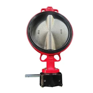 OEM DN300 Worm Gear GGG50 Wafer Butterfly Valve PN16 Manufacturer, ExportersView Specifications
-
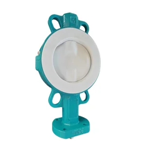 China 4 inch Ductile Iron Split Body PTFE Full Lined Wafer Butterfly Valve Factories, ExportersView Specifications
-
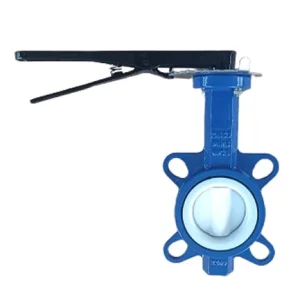 OEM PTFE Seat & Disc Wafer Centerline Butterfly Valve Factory, FactoriesView Specifications
-
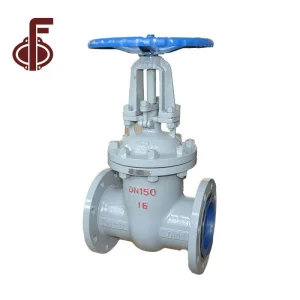 China 150LB 300LB WCB Cast Steel Gate Valve Manufacturer, FactoriesView Specifications
-
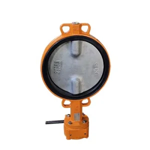 China Worm Gear Operated CF8 Disc Double Stem Wafer Butterfly Valve Manufacturer, ExporterView Specifications
-
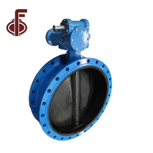 China PN16 CL150 Pressure Flange Type Butterfly Valves Manufacturers, ExportersView Specifications
-
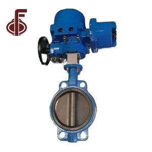 OEM Electric Actuator Wafer Butterfly Valve Factories, ExporterView Specifications
-
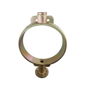 OEM Hot-dip Galvanized Wafer Butterfly Valve Body Manufacturer, ManufacturersView Specifications
Large-Bore Penstock Diameter Capability
High Hydrostatic Head Pressure Rating
ISO 5208 Bi-directional Hydro Sealing
Emergency Gravity Counterweight Drop
Hydraulic Plant Dynamics: Main Inlet Valves (MIV) & Penstock Engineering
Evaluating hydrodynamic performance, pressure transient surges (water hammer), and structural resilience under continuous multi-megawatt operational loads.
Main Inlet Valve (MIV) Turbine Protection
In modern hydroelectric power stations (Francis, Kaplan, and Pelton installations), the Main Inlet Valve serves as the decisive safety barrier situated upstream of the turbine spiral casing. When operating under static heads ranging from 30 meters up to 350 meters, bi-eccentric and triple offset butterfly valves (TOVs) supersede conventional gate valves due to their compact face-to-face dimensions, superior throttling controllability during dewatering, and rapid emergency closure capabilities.
Our factory specializes in bi-plane lattice disc configurations that optimize flow lines, drastically lowering the local drag coefficient (ζ ≤ 0.12 to 0.18 when fully open). By minimizing localized eddy turbulence and downstream pressure drop, power plants recapture thousands of megawatt-hours annually while preventing flow-induced structural vibrations in powerhouse substructures.
- Disc ProfileBi-Plane Flow-Through / Lattice Design
- Operating MediumUntreated River Water, Sediment Slurry, Glycol Coolants
- Closing MechanismOil-Pressure Hydraulic Cylinder + Drop Counterweight
Penstock Rupture Emergency Isolation Systems
Penstock safety isolation requires valves capable of executing trip closures under peak runaway flow rates without electrical grid power. In the event of a downstream pipe rupture or catastrophic generator load rejection, flow velocities can surge up to 300% of nominal design values. Our heavy-duty hydraulic drop-weight butterfly valves leverage gravity-driven potential energy to achieve fail-safe isolation within 8 to 25 seconds.
To prevent lethal hydraulic transients (water hammer shocks characterized by the Joukowsky equation ΔP = ρ · a · Δv), our valves integrate dual-speed oil damping accumulators. The initial 70% of closure occurs rapidly to curb surging flow, while the final 30% engages high-resistance throttling dampers, cushioning the valve disc into its seat and dissipating kinetic energy safely.
- Safety ActuationFail-Safe De-energized Gravity Weight Drop
- Water Hammer MitigationSegmented Two-Speed Controlled Hydraulic Dashpot
- Emergency Closing TimeAdjustable from 8 to 45 Seconds
| Valve Architecture | Suitable Hydro Head (m) | Flow Resistance (ζ) | Sealing Technology | Primary Powerhouse Application |
|---|---|---|---|---|
| Concentric Resilient Seated | Low Head (< 60m) | 0.25 – 0.35 | Replaceable EPDM / NBR Booted Seat | Cooling Water Systems, Tailrace Isolation, Drainage Skids |
| Double Eccentric (High-Performance) | Medium Head (50 – 200m) | 0.16 – 0.22 | Stainless 316 / Flexible PTFE Composite Ring | Turbine Guard Valves, Penstock Manifold Branches |
| Triple Offset Metal-to-Metal (TOV) | High Head (150 – 450m+) | 0.12 – 0.18 | Laminated SS316 + Graphite / Stellite 6 Hard-Face | Main Inlet Valve (MIV), Pumped Storage Turbine Isolation |
| Bi-Plane Spherical Lattice Disc | Ultra-High Flow / Penstocks | 0.08 – 0.14 | Hydraulically Activated Retractable Bronze Seal | Large-Diameter Main Dam Bottom Outlet Conduits |
Combatting Silt Abrasion, Cavitation Erosion, and Lifecycle Fatigue
Advanced metallurgy configured for run-of-the-river silt discharge and severe hydrodynamic pressure drops across global hydroelectric basins.
Severe Silt & Sediment Hard-Facing
Hydro plants situated along sediment-dense river basins (such as the Himalayas, Andes, and Yellow River basins) experience severe quartz-particle erosion. Suspended sediment acts as high-velocity liquid sandpaper against sealing faces.
We implement automated high-velocity oxygen-fuel (HVOF) supersonic spraying and laser cladding of Tungsten Carbide (WC-Co-Cr) and Stellite alloy overlays (minimum 58 HRC hardness). Disc sealing perimeters receive CNC micro-lapping to maintain absolute bubble-tight shutoff even after passing millions of cubic meters of hard sediment.
Cavitation Mitigation & Aeration
When throttling high-head bypass water, localized static pressures can drop below the fluid vapor pressure, triggering catastrophic cavitation pitting along disc rims and downstream liner walls.
Our factory utilizes Computational Fluid Dynamics (CFD) parametric modeling to sculpt hydrodynamic disc cambers and anti-cavitation perforated vane trims. Integrated vacuum breaker aeration valves introduce controlled atmospheric air into the separation zone immediately downstream, cushioning micro-bubble collapse and arresting vibration damage.
Casting Integrity & Cryogenic Toughness
Valve pressure boundaries in alpine regions must withstand low ambient conditions down to -40°C without brittle transition failures. Cast bodies are produced in high-grade carbon steel WCB/WCC, low-temperature LCC, or martinsitic stainless steel CA6NM (13Cr-4Ni).
Every primary pressure casting undergoes 100% Non-Destructive Testing (NDT) via Radiographic (RT), Ultrasonic (UT), and Magnetic Particle (MT) inspection in accordance with ASME Section VIII and EN 10204 3.1 / 3.2 inspection certification for complete metallurgical traceability.
Global Regulatory Assurance & The Smart Hydropower Valve Era
Aligning Chinese heavy valve manufacturing precision with international project compliance, IoT condition monitoring, and digital twin asset optimization.
International Code Compliance & Factory Acceptance Testing (FAT)
For international EPC contractors (PowerChina, GE Hydro, Andritz, Voith, Toshiba), cross-border procurement requires uncompromising adherence to global standards. Tianjin Zhongfa Valve Co., Ltd. builds and tests all hydro-grade butterfly valves to:
- Design StandardsEN 593, AWWA C504, ISO 10631, ASME B16.34
- Flange Drill PatternsEN 1092-1 (PN10/16/25/40), ASME B16.47 Series A, JIS B2239
- Shell & Seat Hydro TestISO 5208 Rate A, API 598 (Zero Allowable Leakage)
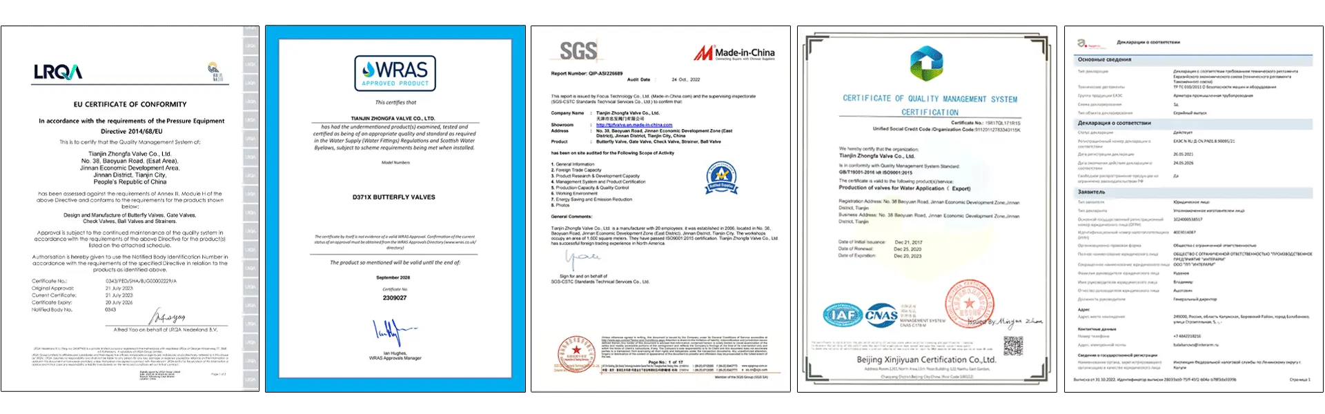
- Safety CertificationsCE-PED (2014/68/EU), SIL-2 / SIL-3 Functional Safety Ready
- FAT VerificationDNV, Lloyd's Register, Bureau Veritas, SGS Witness Inspection
Engineering Support & Lifetime Site Commissioning
Exporting large-bore valves requires comprehensive lifecycle technical coordination. Our dedicated engineering division supports hydro operators from concept through post-commissioning maintenance:
- FEA Structural StressAnsys Workbench Stress & Disc Natural Frequency Modes
- Transient CalculationsWater Hammer Wave Speed & Air Release Dynamic Sizing
- On-Site SupervisionCertified Field Engineers for Flange Alignment & Hydraulic FAT
- Spare Parts AssuranceGuaranteed 25-Year Availability of Seal Rings & Bushings
- Custom OEM PortingIntegrated Bypass Equalizing Valves & Locking Counterweights
Embedded IoT Micro-Sensors
Integrating fiber-optic acoustic emission transducers within valve body castings to identify micro-cavitation bubble bursts prior to metallurgical surface loss.
Smart Self-Tuning Actuation
Closed-loop servo hydraulic power units dynamically modifying closure speeds based on live penstock differential pressure sensor telemetry.
Real-Time Fatigue Life Tracking
Cloud-synchronized FEA models tracking cycle counts, stress harmonics, and packing seal degradation to provide accurate predictive maintenance scheduling.
Laser-Clad Nano-Structured Alloys
Ultra-dense nanostructured Ni-Cr-Ti carbide surface matrices delivering 5x resistance against extreme silt abrasives in pumped storage generating circuits.
Hydro Power Butterfly Valve Engineering Insights
Direct answers to the most rigorous technical queries submitted by hydro station procurement directors and consulting engineers.
When should a power plant select a butterfly valve over a spherical valve for Turbine Main Inlet (MIV) service?
Butterfly valves are the premier, cost-effective choice for medium and low-head hydro plants (typically heads up to 250 – 300 meters, and DN up to 4000mm). Compared to spherical (rotary ball) valves, double flanged butterfly valves offer a significantly smaller footprint, up to 60% lower overall weight, and roughly 40-50% reduced capital investment for the valve, actuator, and powerhouse foundation works. Spherical valves are generally reserved for ultra-high heads (> 350-400m) where total open-bore head loss must approach absolute zero.
How does the hydraulic drop-weight counterweight system guarantee fail-safe emergency closure?
The counterweight system operates entirely on gravitational potential energy without depending on external alternating current (AC) electrical supplies. During normal plant operation, an electro-hydraulic power unit (HPU) maintains the counterweight in an elevated, latched position. Upon receipt of an emergency trip signal (or during complete powerhouse station blackout), a DC solenoid valve or mechanical trip release opens, allowing the massive counterweight to descend smoothly. The descent is precisely regulated by a dual-stage oil dashpot cylinder, closing the disc without generating excessive transient surge pressures.
Why is a bypass equalizing valve system critical prior to opening a main turbine butterfly valve?
Attempting to crack open a large-diameter butterfly valve under high differential pressure (ΔP) exposes the disc and seat seals to enormous hydraulic shear torque and destructive high-velocity cavitation jets. A synchronized bypass valve (usually DN50 to DN250 depending on conduit size) opens first, filling the turbine spiral case and equalizing the pressure upstream and downstream of the main valve disc. Once differential pressure drops below 5-10% of total head, the main valve opens smoothly under low-torque conditions, drastically extending seat life and protecting the hydraulic actuator.
What measures does Tianjin Zhongfa Valve implement to prevent trunnion bearing seizure?
Hydroelectric valves often remain stationary in the fully open position for months or years before being commanded to close. To prevent bearing galling, corrosion seizure, or cold adhesion, our factory uses maintenance-free, self-lubricating sintered bronze bushings impregnated with solid PTFE/lead-free lubricants, or high-load synthetic matrix composites. Stems are constructed from high-tensile 17-4PH or 2Cr13 stainless steel with hard chromium plating or nitriding treatments, ensuring low friction coefficients (μ ≤ 0.08) throughout 30+ years of submerged service.
Can China butterfly valve manufacturers accommodate custom face-to-face dimensions for plant retrofits?
Yes. Powerhouse rehabilitation and turbine uprating projects frequently encounter legacy penstock flanges built to obsolete regional standards or non-standard face-to-face dimensions (e.g., DIN 3202 F4, BS 5155, or custom legacy turbine vendor dimensions). With our internal 3D modeling, flexible casting patterns, and heavy CNC boring mills, we engineer custom bodies, custom flange offset drillings, and integral dismantling joints that fit precisely into existing penstock galleries without necessitating pipe cutting or civil powerhouse modification.
Auxiliary Plant Flow Control & System Protection Valves
Engineered for penstock drainage, draft tube dewatering, powerhouse cooling loops, and high-pressure oil lubrication networks.
-
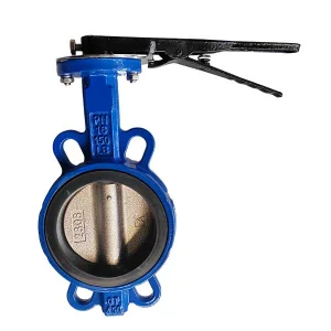 OEM PN16 5K 10K 150LB Hard Back Seat Wafer 4 Butterfly Valve Manufacturer, FactoriesView Specifications
-
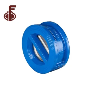 OEM DI CI SS304 Dual Plate Check Valve Manufacturer, ExporterView Specifications
-
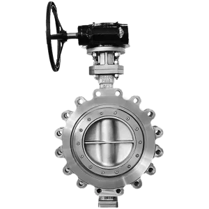 OEM Lug Type Triple Offset Butterfly Valve Factories, ExportersView Specifications
-
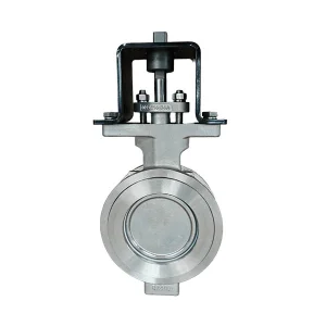 China CF8 Wafer High Performance Butterfly Valve with Support Manufacturers, FactoriesView Specifications
-
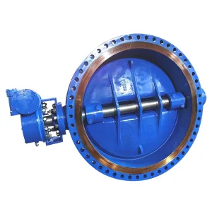 OEM Short Pattern U Shape Double Eccentric Butterfly Valve Factories, ExportersView Specifications
-
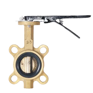 OEM Brass Bronze Wafer Butterfly Valve Manufacturer, ManufacturersView Specifications
-
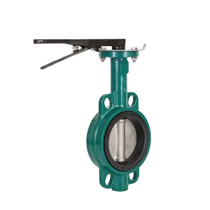 China Cast Iron Wafer Type Butterfly Valve Manufacturers, FactoryView Specifications
-
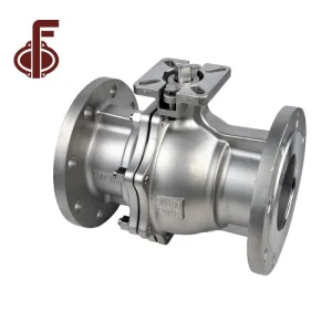 China Stainless Steel Flange Type Floating Ball Valve Factory, ExporterView Specifications
Initiate Your Hydro Flow Control Engineering Specification
Collaborate with our senior hydraulic valve engineering division. We provide complete 3D CAD models, finite element stress reports, water hammer transient analysis, and customized OEM quotations within 24 hours.